Use this property grid to configure an aggregated carrier of up to 32 component carriers. To configure the individual component carriers refer to the following:
Advanced LTE-A Pro FDD E-UTRA Downlink CC
Advanced LTE-A Pro FDD eMTC Downlink CC
Advanced LTE-A Pro FDD NB-IoT Downlink CC
Although you can have up to 16 carriers in your waveform, only one of them may be an aggregated carrier (LTE-A). Therefore, once you have added an aggregated carrier to your waveform setup, all of the LTE-A carrier choices become grayed out. If you want to use a different LTE-A carrier, first delete the current carrier aggregation from the waveform setup.
Click this button to open a drop-down list from which you can select a carrier to add to the setup table. The carrier is inserted above the currently selected carrier in the table. The maximum number of carriers is 16. You can also make older carrier versions available by clicking View > Show Legacy Carrier from the menu bar.
For Advanced waveforms, if Waveform Generation Length is >160 ms, the Add Carrier and Copy Carrier buttons will not work. Refer to the Carrier n node's topic for Uplink or Downlink. Waveform Generation Length's >160 ms is not available for all 3GPP Advanced waveforms.
Long waveform generation requires N5172B/82B with firmware version ≥B.01.10.
Click this button to delete the currently selected carriers in the setup table. You can highlight multiple carriers by holding down the CTRL key while selecting the carriers. You can also use the SHIFT key to select a succession (group) of carriers.
Click this button to quickly add a copy of the selected carrier to the carrier configuration summary table.
For Advanced waveforms, if Waveform Generation Length is >160 ms, the Add Carrier and Copy Carrier buttons will not work. Refer to the Carrier n node's topic for Uplink or Downlink. Waveform Generation Length's >160 ms is not available for all 3GPP Advanced waveforms.
Long waveform generation requires N5172B/82B with firmware version ≥B.01.10.
Choice: On | Off
Default On
Click in the cell and use the drop-down arrow to select either On or Off.
|
On |
The Frequency Offset and Cell ID values are automatically set by the software. The Cell ID is set to the same value as the Component Carrier index number. |
||
|
Off |
Manually set the Frequency Offset and Cell ID values. |
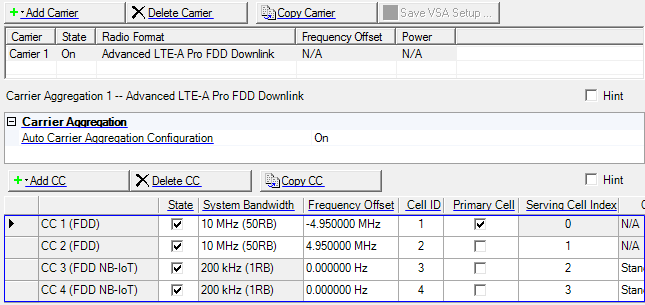
This table enables you to view the key parameters for each component carrier in the aggregated carrier. You can add or delete component carriers using the buttons above the table (see descriptions below). Displayed parameters will vary, depending on the component carrier configuration, and some can be conveniently edited directly in the table. You can use a maximum of 32 component carriers.
Opens a ![]() drop-down list
from which you can select a component carrier to add to the setup table. The carrier
can be inserted above or below the currently selected carrier in the table. The maximum
number of component carriers is 32. You can use
a maximum of 32 component carriers.
drop-down list
from which you can select a component carrier to add to the setup table. The carrier
can be inserted above or below the currently selected carrier in the table. The maximum
number of component carriers is 32. You can use
a maximum of 32 component carriers.
Option Vxx adds the capability to select an Advanced LTE-A TDD component carrier. Refer the N7625B Signal Studio for LTE/LTE-Advanced TDD help for more information.
Deletes the selected carrier from the setup table.
Adds a copy of the selected carrier to the setup table.
Click to enable or disable the component carrier selected.
Choice: 1.4 MHz (6RB) | 3 MHz (15RB) | 5 MHz (25RB)) | 10 MHz (50RB) | 15 MHz (75RB) |20 MHz (100RB)
Default: 10 MHz (50RB)
Double-click or use the drop-down menu to set the system bandwidth and number of Resource Blocks (RB). When you select a system bandwidth, the software automatically adjusts the value in the Total number of Resource Blocks cell and the Total number of Occupied Sub-carriers cell.
The resource blocks and some parameters are reconfigured by changing the System Bandwidth parameter.
Default: 0.000000 Hz
Sets the frequency offset for the carrier relative to the signal generator’s frequency setting.
The range of the parameter is coupled to the Oversampling Ratio, the Base Sampling Rate, the System Bandwidth and the max ARB Sample Clock of the connected signal generator.
Frequency Offset is always editable, even if Auto Carrier Aggregation Configuration is on.
In the case (1) or (2), auto configuration is done for Frequency Offset and Cell ID.
(1) When any action "Add CC" or "Delete CC" or "Copy CC" or Change System BW is done and Auto Carrier Aggregation Configuration parameter is On.
(2) When Auto Carrier Aggregation Configuration parameter is changed to On from Off.
Auto configuration sets Cell ID same as Component Carrier Index.
If Auto Carrier Aggregation Configuration is set to off, auto configuration does not work.
Range: 0–503
Default: 0 with Auto Carrier Aggregation Configuration set to Off
Same as the CC index number with auto Carrier Aggregation Configuration set to On
With Auto Carrier Aggregation Configuration set to Off, enter a cell ID value.
The software uses this value to set the Physical Layer Cell ID group and sector cells:
Cell ID = (3 x Physical Cell ID group + Physical Cell ID sector).
This property is also available in the Uplink node.
Sets the primary cell (PCell) in active component carriers. The primary cell is only one in the component carriers. Component carriers are composed of the primary cell and all secondary cells. If the component carrier for the primary cell is deleted or its state is changed, suitable component carrier for the primary cell is automatically set by the software.
See 3GPP TS 36.331 for more information.
Range: 0 to 31
(Primary Cell: 0, Secondary Cell: 1 to 31)
Sets the serving cell index for the component carrier.
When Primary Cell is set to on in active component carriers, the corresponding Serving Cell Index is automatically set to 0 and is read only.
Otherwise enter a value for the serving cell index.
The Serving Cell Index value is re-assigned whenever you Add CC, Delete CC, Copy CC, or change the Primary Cell.
See 3GPP TS 36.211, 36.212, 36.213 and 36.331 for more information.